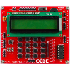
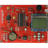
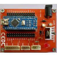
The peripheral kit named as Mini Voyager 2 is peripheral interfacing experimenter board. The main aim of the peripheral board is to depict the ease with which any hardware peripheral can be interfaced with microcontroller using a software application.
Easy to interface with access to individual peripherals.
Software and manual are available for various microcontroller platforms.
Compact in size and portable, can be interfaced with 3.3V and 5V based systems.
| MINI VOYAGER 2 LIST OF PERIPHERALS |
| S. NO. | PERIPHERAL |
| 1 | Buzzer |
| 2 | Multiplexed Switches (Array of 16 switches) |
| 3 | Alphanumeric Display ( LCD 16 X 2) |
| 4 | Shift register with 8 LEDs at output |
| 5 | Real Time Clock |
| MV1, MV2 have been used as experiment kits for AVR and PIC-based courses, following are the experiments undertaken at BSC level |
| EMBEDDED SYSTEM LABS - BSC ELECTRONICS |
| EXP NO. | EXPERIMENT | BOARD REQUIRED |
| 1 | Flash LED at an observable rate. | MV1 |
| 2 | Hello LED – Flash LED at a rate such that the LED appears always on. Estimate the onset of the rate when the LED appears to stay on | MV1 |
| 3 | Controlling ON/OFF of an LED using switch. | MV1 OR MV2 |
| 4 | Use LFSR based random number generator to generate a random number and display it. | MV1 OR MV2 |
| 5 | Toggle the LED every second using Timer interrupt. | MV1 |
| 6 | Use the potentiometer to change the red LED intensity from 0 to maximum in 256 steps. | MV1 |
| 7 | Use the switch to select the LED (from RGB led) and then the potentiometer to set the intensity of that LED and thus create your own color from amongst 16million colors. | MV1 |
| 8 | Read the ADC value of the voltage divider involving the LDR. Print the value on the serial monitor. | MV1 |
| 9 | Use the LDR and estimate a threshold for the LDR value and use that to turn the RGB LED on, to simulate an ‘automatic porch light’. | MV1 |
| 10 | Use the thermistor to estimate the temperature and print the raw value on the serial monitor. | MV1 |
| 11 | Connect the LCD I/O Board and print ‘Hello World’ on the LCD. Scroll display from left to right. | MV2 |
| 12 | Use the on-board EEPROM to store the temperature min and max values together with a time stamp. | MV1 |
The kit was designed and developed at TI-CEPD, NSUT, Delhi.


